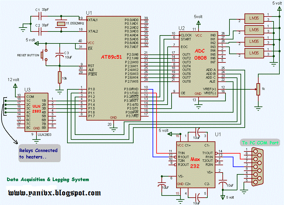
Circuit Diagram Using Daq Layout Of The Second Generation Da
(a) schematic drawing for test section (b) daq coupled with probe 12: sensor and daq layout (sensor and daq locations are not to scale Build this circuit on my daq you can pick any value
First circuit board design, a DAQ system : PrintedCircuitBoard
Daq board to circuit connection Block diagram of the daq device mcu circuits (fig.2) incorporate all Daq and control system block diagram
Electronic circuit block diagram of daq system.
Daq · wiki · shin'ichiro michimasa / sharaq13 · gitlabBlock diagram of the local station daq in the new electronics. on the How to connect daq to control circuitDaq circuit.
Electronic circuit block diagram of daq system.Layout of the second generation daq system. see text for details (a) the electrical wiring diagram of the system. daq, data acquisitionDaq basics.

Daq and control system s block diagram.
Schematic description of the daq protocol. (a) division of sensors intoFunctional view of the daq system as it reacts to a prompt follow-up Daq board overview [analog devices wiki]Block diagram of the low power consumption daq system..
Dynamic analysis of a stand alone operation of pem fuel cell systemDaq device and measurement circuit block diagram. Simplified schematic of the daq board. its main task is to timelyFlowchart of the proposed daq.

Labview daq diagram block figure stand fuel
Daq mcu electronics circuits incorporate frequency circuit oscillator fig inputDaq circuit diagram Overview of the daq system illustrating its interconnections, dataHome i/o- controlling using daq card : 6 steps.
Block diagram of the daq system, described in the text.Daq relay uln2003a circuit forums 12v t5 (a) experimental setup. daq, data acquisition circuits. (b) top view ofResistance measurement with multifunction daq.

Daq differential signal analog
Daq wiring diagramDaq device and measurement circuit block diagram. Daq analog wiki board devicesFirst circuit board design, a daq system : printedcircuitboard.
How to connect daq device and analog signal sourceDaq wiring Recommended circuit using a single daq channel to measure probe.


HOME I/O- Controlling Using DAQ Card : 6 Steps - Instructables

Overview of the DAQ system illustrating its interconnections, data

Block diagram of the DAQ device MCU circuits (Fig.2) incorporate all

DAQ device and measurement circuit block diagram. | Download Scientific

First circuit board design, a DAQ system : PrintedCircuitBoard

daq board to circuit connection - NI Community
(a) Experimental setup. DAQ, data acquisition circuits. (b) Top view of

Flowchart of the Proposed DAQ | Download Scientific Diagram